ME 94: Independent Study: Musical Instruments
Springloaded Clarinet Undercutting Tool
Tufts University Department of Mechanical
Engineering
with Selmer Musical Instruments
Joshua
A. Schultz, EN class of 2002
Jesse "Chip" Jones, project advisor
- Abstract
- Introduction
- Design Process
- Motivation
- Constraints
- Generations of Designs
- Quantitative Data
- Future
Directions
 Abstract:
Selmer Instruments is arguably the best known maker of woodwind instruments in the world. Regardless of your brand name preference, there is likely someone in your musical group who plays a Selmer instrument. Selmer has made great developments in the manufacture of clarinets, and although they are still made by hand, technology has assisted them in making clarinets more quickly and effectively, and with greater precision. The clarinet is an instrument that has come to its present design by a long evolutionary process, some parts of which would not seem logical, had they been implemented all at once at the beginning. But the Clarinet as it is has remained largely unchanged for a number of years, and major changes introduced from a manufacturing perspective would be unacceptable to musicians, who have spent years learning to play and feel comfortable with their instruments.
Perhaps the most time consuming and intricate portion of the manufacture of clarinets is the drilling and placement of the holes. Selmer has made great strides in increasing the speed and precision of this process. The holes are drilled with a drill press, and a mechanical device positions the clarinet joint axially and angularly. This seems straightforward; however, the holes themselves are not simple holes. The holes are undercut – that is to say that they flare outward at an angle and taper as they reach the inner side of the hole. This stabilizes the pitch of the clarinet and is important to intonation and playability. Because the taper is on the inside, it is not accessible directly from the press. As it stood before this project, an angled bit had to be "worked in" to the hole, chucked, do the cutting, then be "worked out," and this be repeated for each hole. It is easy to see that this is the slow part of the process. The goal of this study is to make a tool or tools that will speed up this part of the process.
Abstract Introduction Design Process Future Directions
Introduction:
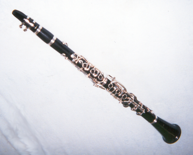
The clarinet is a single reed instrument that evolved from more primitive single reed instruments. Archaeologists have found evidence of many of such single reed instruments in many different cultures. They all basically consist of a single reed and a pipe with holes along its length, which allow the player to play a variety of pitches by covering or uncovering the holes.
So how does a Clarinet actually work...is it free vibration or forced vibration?
The player provides the instrument with air, but does not create any vibratory phenomena himself, as brass musicians do. As the player "tongues" a note, air is released into the instrument. This sudden burst of air causes a flexible reed to deflect. The motion of the reed sends a pulse down the length of the pipe. This pulse is governed by the laws of conservation of mass and energy as expressed in terms of fluid mechanics, leading to the acoustics equations:
![]() ,
,![]()
where the flow of air in the pipe is modeled as a one dimensional plane wave, P(x , t) is the pressure, j is the square root of –1, w is the natural frequency of the pipe (a constant that arises by solving the mass and energy equations by separation of variables) , r 0 is the density of air at atmospheric pressure, c is the speed of sound in air, v(x , t) is the velocity of the air in the tube, and A and B are constants. This is a vibratory solution to the fluid mechanics equations, and we can use boundary conditions to determine w . There can be one of two boundary conditions.
- Closed or "Fixed" end. The moving air hits a wall, and can’t move any further, so the velocity must be 0 at that point.
- Open or "Free" end. If the air is open to the atmosphere at that point, the air is allowed to expand until the pressure is atmospheric pressure, for a relative pressure of 0.
 The "pulse" of
air will be mathematically governed by these boundary conditions, physically
that is to say that it will "reflect" off a fixed or free end
and travel back the other way. A clarinet has one
fixed end at the mouthpiece and one free at the bell. As
the pulse travels back up the pipe, it adds up with other pulses, (that
is their pressures add), and eventually the addition of pressures becomes
spatially distributed in a regular fashion. Some parts, called nodes, do
not change in time, and the rest of the tube has pressures oscillating
in time in a periodic fashion, the parts with maximum amplitude being
called antinodes. The amplitude of the pressure oscillations at each
point and position of nodes and antinodes do not change with time. This
is called a standing wave and is determined by the speed of sound in
air and the length of the pipe. The frequency of this wave in the pipe
is the pitch that you hear. The reed, which is the source of the vibration
can only vibrate at the natural frequency of the pipe. So the pipe is
vibrating in free vibration and the reed is vibrating in forced vibration.
This should make intuitive sense; the player wants to change the pitch,
so he changes the natural frequency of the pipe. He can’t change
the properties of the reed, at least not while he’s playing! Also,
reeds vary in thickness, length, and mechanical properties, but the clarinet
still plays in tune.
The "pulse" of
air will be mathematically governed by these boundary conditions, physically
that is to say that it will "reflect" off a fixed or free end
and travel back the other way. A clarinet has one
fixed end at the mouthpiece and one free at the bell. As
the pulse travels back up the pipe, it adds up with other pulses, (that
is their pressures add), and eventually the addition of pressures becomes
spatially distributed in a regular fashion. Some parts, called nodes, do
not change in time, and the rest of the tube has pressures oscillating
in time in a periodic fashion, the parts with maximum amplitude being
called antinodes. The amplitude of the pressure oscillations at each
point and position of nodes and antinodes do not change with time. This
is called a standing wave and is determined by the speed of sound in
air and the length of the pipe. The frequency of this wave in the pipe
is the pitch that you hear. The reed, which is the source of the vibration
can only vibrate at the natural frequency of the pipe. So the pipe is
vibrating in free vibration and the reed is vibrating in forced vibration.
This should make intuitive sense; the player wants to change the pitch,
so he changes the natural frequency of the pipe. He can’t change
the properties of the reed, at least not while he’s playing! Also,
reeds vary in thickness, length, and mechanical properties, but the clarinet
still plays in tune.
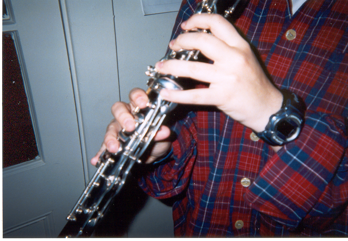
Close-up
of clarinet holes
So what does the hole do, exactly?
The pressurized air is bounded by the walls of the pipe and can not expand. When it encounters a hole, air rushes out of the hole and the air expands until the pressure is equalized, namely, the air is at atmospheric pressure. This means that a "free end" is at the hole; the rest of the air inside the clarinet does not vibrate, although sound waves pass out of the end; secondary, propagating pressure waves that are at the frequency of vibration of the pipe. These are what you hear. The first hole left uncovered is a "free end;" the length of the pipe is from the reed to that hole. This changes as different holes are uncovered.
If you just need a hole, why are they all different sizes? And why the fancy beveled edge on the inside?
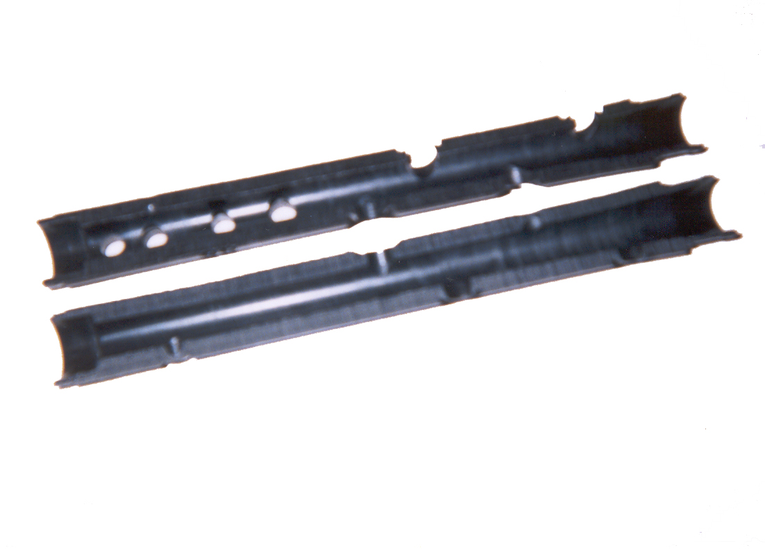
Although open holes act as a free end, it isn't perfectly free. It’s really a mixed boundary condition. The air can’t rush out of the hole all at once. So the flow pattern puts the free end a little beyond the hole. How far downits moved depends on the size of the hole. Since the clarinet, unlike some other woodwind instruments, still depends on the fingers to cover the holes, the holes have to be small enough so that the player can still cover them with his fingers. The hole also can’t be moved up to compensate, as this will affect the hand position of the player. "Undercutting" the hole gives the illusion of a bigger hole and brings the length of the vibrating air column back to what it’s supposed to be. The hole sizes and positions are a result of trial and error; in the days before precision parts, the clarinet maker couldn’t make the hole exactly in the right place, and had to increase the undercutting to fine tune the pitch at certain notes. Selmer mapped out these values and makes them the same for each clarinet. However, the angle and depth are different for each hole.
 |
 |
Clarinet
holes can not be moved. They
are carefully placed to fit the player's hand position |
Split
joint, allowing view of the undercut holes. |
But the undercutting is on the inside...how do you get in to cut it?
Currently, an angled bit had to be inserted into the hole, then twisted upright, then chucked into the drill press. After cutting the angled edge, the bit had to be de-chucked, then twisted out in reverse. This is a very time-consuming process. We at Tufts felt that we could do better, and looked for a "straight-in, straight-out" solution with movable blades.
Motivation:
The goal of this study was to create a tool that could go in and come out without being chucked and de-chucked before and after every cut. This almost necessarily involves retractable blades, which can be controlled from outside the clarinet bore. This way, we can lower the tool into the hole, activate the blades, cut the beveled edge, deactivate the blades, and simply lift the tool out the hole. We can then go to the next hole with a minimum of effort, with both time and work saved. Ideally, the manufacturer could leave one hand on the mandrel that holds the joint, and one hand on the quill.
Constraints:
1. The clarinet setup had been previously constructed and could not be changed. Obviously, the clarinet geometry couldn’t be changed either.
2. The tool must be chucked into the drill press – torque can’t come from any other source.
3. The size of the holes posed much difficulty – making something that small is difficult.
4. We are expected to make a prototype – therefore we are more or less restricted to the capabilities of the Tufts machine shop, as far as geometry, precision and materials.
Generations of designs:
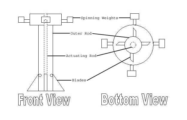
1. Spinout Design
 The
first idea presented was a slender rod with two hinged blades at the
end that would expand outward by
"centrifugal force." If we know the rotational speed of the drill
press, we can calculate how much the blades will expand, and fix an angle
accordingly. However, in addition to gravity, the contact forces with the
hole will also tend to force the blades back in, and this cutting force can
be difficult to measure, and this would most likely become an iterative process.
Anomalies in wood hardness and speed of the drill press could lead to very
inaccurate results. We began to examine ways to create a tool for which,
when the blades were extended, would have a negligible deflection due to
cutting forces.
The
first idea presented was a slender rod with two hinged blades at the
end that would expand outward by
"centrifugal force." If we know the rotational speed of the drill
press, we can calculate how much the blades will expand, and fix an angle
accordingly. However, in addition to gravity, the contact forces with the
hole will also tend to force the blades back in, and this cutting force can
be difficult to measure, and this would most likely become an iterative process.
Anomalies in wood hardness and speed of the drill press could lead to very
inaccurate results. We began to examine ways to create a tool for which,
when the blades were extended, would have a negligible deflection due to
cutting forces.
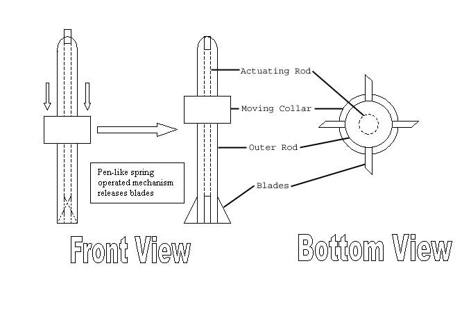
2. The Wedge:
 Two
blades are held inside the central column by springs. They are driven
out by a wedge inside the central column. The wedge holds them in this
position against the cutting force, giving minimal deflection, as no
bending stresses are present due to the symmetry of the blades on each
side. When the wedge is disengaged, the blades spring back inside the
central column, and the tool can be lifted out. This design was modified
a few times as more peripheral issues were considered. We added a collar,
which would engage the wedge when it came in contact with the clarinet’s
surface. At first, we planned to do this with levers, as the upward motion
of the collar with respect to the rest of the tool would have to be translated
into downward motion of the wedge. We found it was much simpler to have
two pieces that push together as the operator lowers the quill, with the
wedge on the top piece and the blades on the bottom. This complicates
things in that power needs to be transferred from the top to the bottom,
but this is not impossible.
Two
blades are held inside the central column by springs. They are driven
out by a wedge inside the central column. The wedge holds them in this
position against the cutting force, giving minimal deflection, as no
bending stresses are present due to the symmetry of the blades on each
side. When the wedge is disengaged, the blades spring back inside the
central column, and the tool can be lifted out. This design was modified
a few times as more peripheral issues were considered. We added a collar,
which would engage the wedge when it came in contact with the clarinet’s
surface. At first, we planned to do this with levers, as the upward motion
of the collar with respect to the rest of the tool would have to be translated
into downward motion of the wedge. We found it was much simpler to have
two pieces that push together as the operator lowers the quill, with the
wedge on the top piece and the blades on the bottom. This complicates
things in that power needs to be transferred from the top to the bottom,
but this is not impossible.
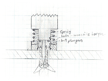
3. The Ballpoint Cutter:
 This
has similar geometry to the Wedge design, incorporating the collar, but
the wedge has been replaced with an inner cylinder so that the blades
can merely be "in" or "out"
when the cylinder is down, it forces the blades out, when it is up out of
the way, they are pulled back in by springs, as before. The inner cylinder
is controlled by a
"click ball point pen" mechanism. Each time the collar comes in
contact with the clarinet surface, it functions as if the operator were clicking
the top of a ballpoint pen; one "click" and the inner cylinder
is down and the blades are engaged. Another "click" brings the
inner cylinder up, the blades disengage and the tool can be pulled out the
hole. This tool, in principle, could engage and disengage without even turning
the drill press off. This seemed to be the tool of choice, until the drawings
of the clarinet came.
This
has similar geometry to the Wedge design, incorporating the collar, but
the wedge has been replaced with an inner cylinder so that the blades
can merely be "in" or "out"
when the cylinder is down, it forces the blades out, when it is up out of
the way, they are pulled back in by springs, as before. The inner cylinder
is controlled by a
"click ball point pen" mechanism. Each time the collar comes in
contact with the clarinet surface, it functions as if the operator were clicking
the top of a ballpoint pen; one "click" and the inner cylinder
is down and the blades are engaged. Another "click" brings the
inner cylinder up, the blades disengage and the tool can be pulled out the
hole. This tool, in principle, could engage and disengage without even turning
the drill press off. This seemed to be the tool of choice, until the drawings
of the clarinet came.
4. The Mole: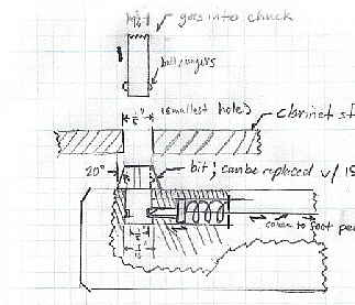
We considered the possibility of going up the bore of each joint and cutting each hole in turn from the inside. This design consisted of the actual cutting tool being in two parts. One part would simply be a rod chucked into the drill with two ball plungers at the end of it. The second part would actually do the cutting and have a ground edge with the correct geometry. A holder positions the second part beneath the chuck, coming through one end of the joint. When the appropriate hole is moved into position, the rod is lowered through the hole and the ball plungers snap into position. A latch inside the holder holds the cutting part of the tool into the holder, and this is disengaged by a foot pedal. The bottom piece rises with the top to do the cutting. When the cutting is done, the bottom part of the tool is lowered back into its place inside the holder, the latch is re-engaged, and under tension, the ball plungers snap out, and the two pieces separate, allowing the top part to be lifted out. A tricky factor would be making sure that the two pieces did not shear apart as the cutting surface comes in contact with the clarinet joint. Unfortunately, in the Selmer setup, both ends of the joint are held in collets, and neither end is accessible. This brought us back to a through the hole design.
Quantitative Data:
Upon receiving drawings of the clarinet from Selmer, it became apparent that each hole could be described by three parameters: its diameter D, the angle of undercutting f , and the depth of undercutting h d . The depth of undercutting can be positive or negative.
If a through
the hole design of some nominal diameter is inserted, how long does the
blade need to be to cut all it needs to cut?
The blade can be analytically, if not physically divided into three parts.
The upper part (h i ) is the part that does not come in contact
with the work due to the difference in diameter between the tool and
the hole. The second part (h d )
cuts all undercutting above the top tangent point of the circular bore. This
will be negative if the depth is negative. The lower part ( d )
is the part that cuts the portion that is due to the curvature of the
circular bore. The sum of these three terms is the blade equation, expressed
in terms of these three parameters. It is derived from geometrical considerations.
h t is the total length of the blade, D is the diameter of the hole, d is the diameter of the tool, f is the angle of undercutting, h d is the depth of undercutting, and Ri is the inner radius of the joint.
If there are two blades inside the column, the maximum width of the blades is d/2. This sets a limit for blade height of:
![]() .
.
Of course, this must have some margin involved, so the max would be less than this value. By comparing this with the values from the blade equation, we were able to size the tools for each hole
See Tool Chart for Hole Sizes (you will need Acrobat Reader to view this document)
As a prototype, we decided to make the purple tool. As the largest, it would be the easiest to make. We returned to the "Wedge" idea, but it is really just a cylinder sliding inside another with a pointed edge to make it actuate the blades more easily. It is made up of a bottom piece that holds the blades, a top piece, which is chucked into the drill press, and a cap, which holds the two together when the blades are disengaged. A simple pin spring loaded locking mechanism holds the top piece down, keeping the blades engaged, which must be released by hand. A triangular prismatic joint allows the two pieces to slide together and apart, and also transmits the torque from the top to the bottom piece.
Drawings of Prototype: (you will need Acrobat Reader to view these documents)
Clarinet
Bottom.pdf
Clarinet Top.pdf
Clarinet Cap.pdf
Pictures of Prototype: ( not complete, just gives an idea)
Future directions:
Our
prototype was made from plastic; the actual tool will likely be
made from stainless steel. Tufts University does not posses tooling
for stainless and this will need to be sent out. Attaching the
blades will be a different matter entirely in this new material
and needs to be investigated. Disengaging the locking mechanism
automatically should be examined. The tool must be tested. Creating
a tool with variable angles could improve the process even more.
It was even suggested that we make at tool which has a double sided
blade; tip drills a pilot, the bottom edge reams out the hole diameter,
then the top edge does the undercutting. This, of course would
require variable angle tools. Selmer also wishes to CNC machine
their clarinets, so at some point this tool will be on a rotating
drum and actuated by solenoids.
Special
Thanks to: Chris French, Selmer Inc., Chip Jones, Jumbo, and Julia
Krummenauer
Questions? Comments? Incredibly sophisticated humor?
email me at jerichowarrior@netscape.net