The Effects of Pallet Size on
Pluck and Windflow
in a Pipe Organ
Adam Sharp
Sponsored by: C.B. Fisk • Special Thanks to: Chip Jones, Tufts University
Abstract:
Due to direct mechanical connections inside a pipe organ, changing one thing can affect another. By increasing the size of the pallet more air can be delivered to the pipes. This effects the way the key feels when it is pressed (the pluck). The goal of this is to build an experimental setup which will allow us to measure the relations between the size (varying both length and width) of the pallet with the volumetric flow rate of air and the pluck of the key.
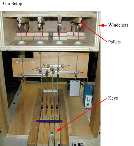
Organ Basics:
The lower section of the windchest (the pallet box) is under constant pressure from air in the bellows. The upper section of the windchest (the wind channel) is at atmospheric pressure and is connected to the pipes. The pallet acts a valve between the lower and upper sections of the windchest. When the key is depressed there is a direct mechanical connection that pulls the pallet away and allows air from the bellows to flow into the pipes. When air flows across the mouth of the pipe it "speaks" and this is what we hear as music.
(Put your cursor over the picture below to see what happens when the key is pressed.)
Introduction:
C.B. Fisk has been making organs since 1961. They are one of only a handful
of companies that are trying to stay true to historical methods of organ building.
Historically, all connections from the keyboard to the pallets were via direct
wires and rollers. Recently many companies have been using the keys as buttons
to activate the pallets. For the player this is a problem because it doesn't
give them any feedback from what's happening in the organ and therefore doesn't
give them the control they want. For the builder using electronics is considered
the easy way out; it's cheating.
The player also requires that the organ produce all its notes with equal loudness.
For example, you wouldn't want a bass note to be barely audible while a high
note is so loud it scares everyone out of the concert hall. The builder must
attack this problem by varying pressures in different windchests and varying
the sizes of the pallets. A low note requires more air than a high note to
speak at the same volume and therefore a larger pallet and/or greater windchest
pressure.
As the size of the pallet increases, the force exerted on it by the air in
the windchest also increases (Force=Pressure*Area). This directly effects
how much force is required to press the key. As soon as the pallet leaves
its slot air rushes around it. According to Bernoulli's Principle, the curve
of the streamlines around the pallet will produce a lift force which also
is passed down through the key. The farther the pallet is from the slot the
less the streamlines must curve and the less force is transmitted into the
key.
The goal is to create a setup that is capable of measuring the outlet air velocity,
the force exerted on the key, and the position of the key simultaneously
and in a repeatable manner.
Experimental Parameters:
-Pallet Length: 8" 9" 10" 12"
-Pallet Width: 1/4" 5/16" 3/8" 1/2" 5/8" 3/4"
-Wind pressure: 2.25 3.25 4.25 6 (inches of water)
-Outlet diameter: 5/16" 1"
C.B. Fisk has provided us with all 24 different sets of pallets and slots
that are all interchangeable within our test setup. They have also provided
us with a blower and bellows so we can provide air at constant pressures (which
can be changed merely by adding more weight to the top of the bellows.)
The two different outlet diameters are to replicate the wind requirements of
a single middle C (5/16"), or of a variety of notes being played at once
(1"). These were machined at the Tufts Machine Shop, to be interchangeable
and to also mount the air speed probe.
Experimental Setup:
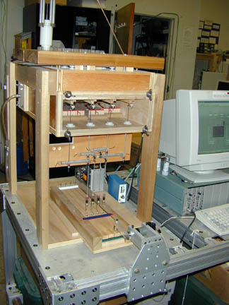 The model organ was supplied to us by C.B. Fisk. It consists of 4 keys, which
will each correspond to a pallet with a different length (but same width) in
each setup.
The model organ was supplied to us by C.B. Fisk. It consists of 4 keys, which
will each correspond to a pallet with a different length (but same width) in
each setup.
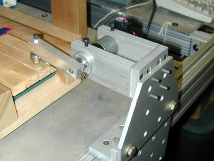 The
robotic finger is a cantilever beam attatched to the shaft of a servo motor
with encoder and controller. At the end of the beam is a piezo-electronic force
sensor. It is all mounted on a manual traverse which locks into place with
a quick-release handle so it can be moved quickly from one key to another.
The
robotic finger is a cantilever beam attatched to the shaft of a servo motor
with encoder and controller. At the end of the beam is a piezo-electronic force
sensor. It is all mounted on a manual traverse which locks into place with
a quick-release handle so it can be moved quickly from one key to another.
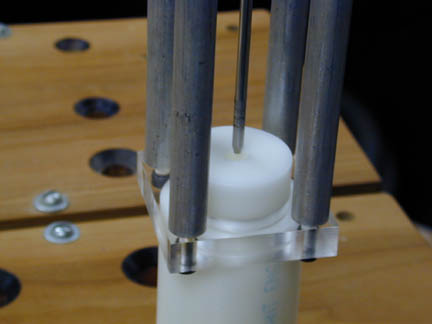 The outlets are machined from 2" Delrin round stock. They lightly press-fit
into plexi-glass bases that have been screwed to the top of the organ. A holder
for the hotwire probe press-fits over the top of each outlet.
The outlets are machined from 2" Delrin round stock. They lightly press-fit
into plexi-glass bases that have been screwed to the top of the organ. A holder
for the hotwire probe press-fits over the top of each outlet.
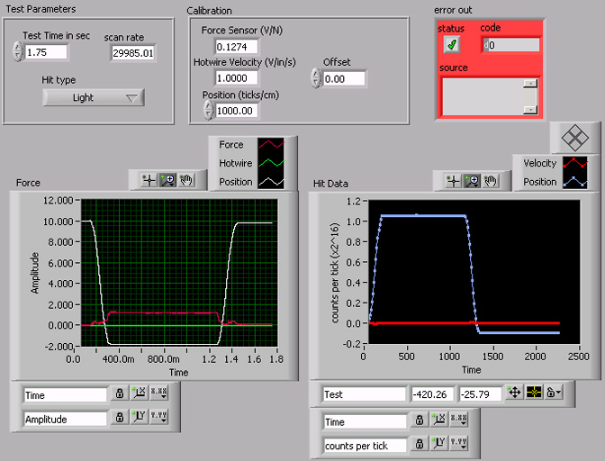
Voltages from the motor encoder, the force sensor, and the hotwire probe all
feed into a National Instruments DAQ card. These voltages are read by the same
LabVIEW program that controls the movement of the finger. From this data we
can plot the force and flow vs. position (pluck), and look for trends in the
data.
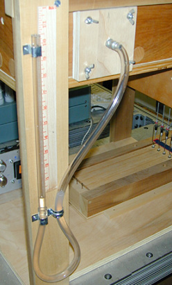 A
simple manometer mounted on the side gives us a reading of the gauge pressure
in inches of water.
A
simple manometer mounted on the side gives us a reading of the gauge pressure
in inches of water.