This section describes the experimental setup. For the
most part, only one setup was used and so it will be the only
one discussed in this section. If data from different setups
becomes pertinent or draws differnent conclusions those
deviations from this main setup will be explained.
Below is a schematic of the airflow through the system.
The air enters the system already compressed to 75 psi (± 25
psi). It then reaches a Bellofram Type 70 pressure regulator
thats range is from 0 - 2 psig (figure 2). It is here that
the pressure is stabilized and adjusted to enough to just
begin the reed's oscillation.
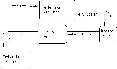
Figure 1: Flow Chart of Air through System
Leaving the regulator, the air pressure is
constant. From here the air travels to the incense. Incense
is used to produce particles in the flow that will influence
the clarinet negligibly but make the flow visible to the
naked eye. The incense is lit and then put into a copper
section of pipe that is part of the flow path. From here, the
smoke laden air proceeds to the smoke filter (figure 2). This
is a very rudimentary filter that consist of a chamber
through which the air passes that is filled with steel wool.
This does a sufficient job at removing tar and other
unnecessary or detrimental by products of burning the
incense, such as tar.
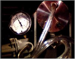
Figure 2: Pressure Regulator (Left) &
Filter (Right)
From the filter the air finally reaches the
artificial embouchure (figure 3). Here the smoke filled air
is forced through the clarinet mouthpiece much in the same
way that a player forces air from his mouth through the
clarinet. However, having a clear embouchure gives us the
opportunity to use video to view the path of the smoke
particles ( and indirectly the air flow ) through the
mouthpiece.
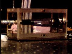
Figure 3: Artificial Embouchure and Clear
Mouthpiece.
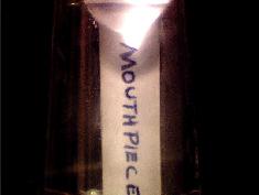
Below is are views of the mouthpiece as it is
seen by the camera while taking data. This first view shows
the air column at the bottom of the mouthpiece. The paper
reading "MOUTHPIECE" is in place to give an idea of
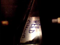
size and visibility of the flow in this section. In the next
picture, the reed channel is shown. Here it is more evident
that problems arise from optical issues due to the way that
the plastic bends the light leaving the mouthpice. It can be
seen from the picture that the paper here reads "REED
CHANNEL," but only the top half of the letters of
"channel" are visible. The "reed" in this
picture is also warped and skewed.