Edward Sensor Hands:The Techno Gloves
The first step taken by the group was to break the project into three major components: creation of an original song, design of the circuits and max patch, and physical construction of the gloves. While each group member helped with each section of the project, the leadership of each section was divided between the three of us. I have a good amount of practical experience with circuits and computer programming, so I was the head of the circuits and max patch section. Alex is a mechanical engineer and also very good at putting things together. For that reason he became in charge of the gloves. Fernando has taken many music classes taken at Tufts and has extensive previous experience using Reason, so he became the lead in the song section.
The first thing I dealt with was working with the different sensors. In our last project we used the flex sensors and they had worked very nicely, so they were taken directly from the last project and soldered to wires. Flex sensors are variable resistors that change resistance when squeezed, so a simple voltage divider circuit is used. Though this doesn’t give voltages of 0-5 Volts, and the corresponding 0-127 values of MIDI data, the numbers could be scaled and normalized in Max. This introduces the proper range of values, but the resolution is poor, but this was a problem that we could deal with.
Next the distance sensor was tinkered with. The distance sensor gives differing voltage levels based on the distance of the closest object it is facing. This circuit essentially just needed to be plugged into +5 Volts and ground and the third wire spat out the voltages. In max these values went from roughly 40 to 120, so these two were scaled to fit the appropriate range. Later, the distance sensor stopped working. I think at this point that it broke because the ground and +5 volt line were mixed up, essentially frying the internal circuitry.
The last sensors we tested were the tilt sensors. When they were ordered, it was believed that they were continuous, meaning they could give changing voltages based of the level of the tilt on the sensor. This in fact turned out to be untrue. They simply acted as switches, turning on when they were tilted more than 45 degrees. In addition they were incredibly small, didn’t fit into any common holders, and hard to solder to. Once tested, these devices were immediately scrapped, leaving us with two less sensors to work with. The broken distance sensor then left us with only 5 of the 8 sensors we planned on, and so the operations of the remaining five had to be changed.
The last sensors experimented with were the Force Sensing Resistors (FSRs). These were little circles with a small lead that gave a variable resistance once pushed on. Unlike the flex sensors, which we wanted to be continuous, we didn’t use a voltage divider circuit. We simply hooked one end into the 5 volt line and the other into the note in space on the Doepfer box. Once squeezed a small amount they would turn the note on with a velocity of 127. These were to be used to control the musical lines of the song.
While this was happening, the song was written and brought into the lab. It had five instruments/musical lines: drums, congas, bass, strings, and synthy lead line. The piece was five loops written in the internal sequencer of Reason. When the project was decided on, there was no mention of how the musical lines were to be controlled. At first I assumed they would be MIDI sequences controlled inside of MAX. But because the entire piece was written in Reason, which doesn’t output very useful MIDI files, it was decided the best way to control the song was to just turn on and off constantly moving musical lines instead of allowing the user to cycle through the notes individually. Using the mute buttons on the mixer of Reason was easy to implement and very effective. We didn’t feel that we were settling for a lesser idea at this point. By controlling the mutes, the song was always perfectly on beat and could be played by anyone. •
Also, with the song written, the different parameters of the left hand glove could be set. The thumb controlled one of the many "interesting" parameters on the Malstrom that produced the string sound. The pointer finger controlled a Malstrom knob and the feedback on the flanger associated with the lead line. The middle finger controlled the frequency of the low-pass filter associated with the bass. The ring and pinky finger controlled a delay and a flange, respectively, coupled to the drums.
Because of the nature of the instrument, many of the blocks used in MAX to control the song were similar or the same. There were five identical finger sensors on each hand, so only two original blocks had to be designed. The blocks to treat the data coming from the flex sensors were incredibly simple. The data coming in from those circuits gave MIDI data from about 90 when straight, to 30 when bent. We needed values of 0 when straight, 127 when bent. To do this we subtracted 90 from the incoming data, and multiplied it by a factor of roughly negative two or three. Sometimes the values dipped below zero or went higher than 127, but the controllers we were working with took the negative values to be zero and the high number to be 127.
The blocks used to turn on and off the mutes were much more involved and counterintuitive. Most of the problems arose from the simple fact that notein, bangs, comparisons, and toggles in MAX send data twice every time they’re used. First, there were five fingers, and five note values coming in, so the circuit checked to see if the note number was the one associated with the block. This controlled a switch that let through a bang if it was the right number. This was connected to a toggle and a counter. The counter was set to two and was wired so that a bang would restart the counter. The counter sent a bang when it reached two and activated the toggle. This toggle was connected another switch, which in turn was connected to another toggle. This toggle was the one that actually toggled between sending note on’s and off’s. These notes were fed directly into Reason on channel 1 to the mixer, which turned on and off the mutes.
Although this solution worked, it wasn’t without its peculiarities. Every time the circuit was turned on, every finger must be initialized. This meant that every finger had to be hit a couple of times, then a bang was sent into the counter. This would make one or two of the fingers work. From there every finger that didn’t work needed to be hit an odd number of times, and the ones that did work an even number of times. The bang to the counter would then need to be hit again. This would work most of the time. Occasionally the process would need to be repeated for a finger or two. I don’t understand this up to the time of me writing this report. Since it eventually worked after some fiddling, it was left alone.
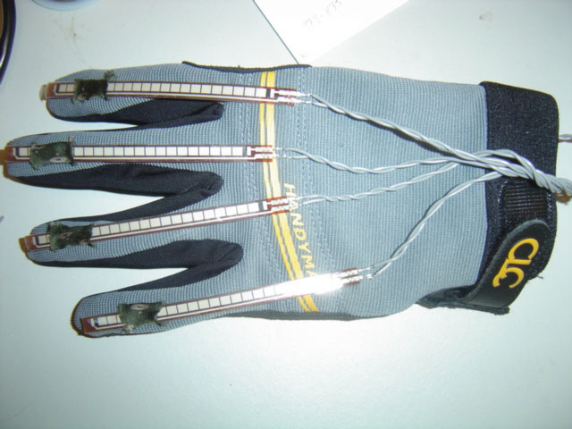
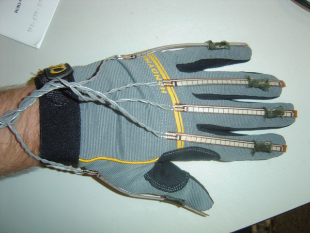
Then the gloves were made. The left hand glove that housed the flex sensors was guessed to be the most difficult, and so was tackled first. The base of the flex sensors were glued to the back of the hand. The tips of the sensors needed to be able to move back and forth, but had to be anchored to the fingertip in some way without restricting its motion. This was accomplished by gluing a small piece of silk to the finger of the glove like a hoop, and the tip of the flex sensor slid through that. The sensors themselves were too jagged on the outside and caught on the silk, and so Alex (with one of the most helpful ideas ever) used rubber cement to glue the plastic from a lunch bag to the outside of the sensors. Because the plastic was skinny it didn’t affect the flex sensors at all and it smoothed out the edges so that they could move easily up and down.
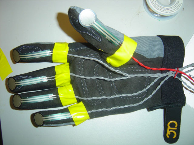
The other glove was much easier. Each FSR was simply glued to the tip of a finger and the base glued and tied to the base of the finger. Each sensor was wired and braided and fed into a small breadboard, which housed the voltage divided circuits of the flex sensors.
The gloves played well, though not perfectly. The FSRs on the tips of the fingers work if the player’s fingers touch the tip of the glove, but otherwise its awkward to play. Also, there is a large amount of latency between when an FSR is released and when the mute of the appropriate channel occurs. This most likely stems from the fact that our Reason patch uses an incredible number of modules. Lastly, the flex sensors still get hung up sometimes and need to be pushed to realign themselves.
This project was mostly a success and there are only a few things I would have changed. The number of sensors we wanted to originally use (13) would have been much too difficult to work with at this point, and so the loss of three of them was beneficial. Even with the 10 we had there were frustrating moments when we couldn’t keep track of everything. The FSR’s don’t seem to like being glued down and bent, so another type of switch or sensor would have been more appropriate. With more time the oddness of the MAX should have been changed to eliminate the "initialization". Otherwise I’m very happy with my group's work and very enthusiastic with our final product. •